Large bore steel piping is one of the specialized products that we offer. Large bore steel pipes are used on various construction engineering initiatives which include ducting and ventilation systems. For custom large bore steel piping, kindly ask us for a quote
Large Bore Steel Piping
Schedule (Wall Thickness)
Length
Pipe ends
- Polyvinyl chloride (PVC)
- Polyethylene (PE)
- Acrylonitrile-butadiene-styrene (ABS)
- Polyamide (nylon)
- Polypropylene
- Threaded ends for screwed joints
- Plain for use with socket type fittings
- Adhesive welded bell and spigot taper joints.
- Plain (unreinforced)
- Reinforced concrete pipe
- Pre-stressed concrete pressure pipe
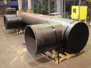 More Wear manufacture pipes from 200mm diameter upwards including specials such as bends (Lobster back), reducers, tee pieces, pipes include flanged or plain for site welding or coupling. Finishes come in a wide variety of coatings including bitumen wrapped, copon painted and galvanizing.
Large bore steel pipework and pipe specials are a More Wear specialty. From 150mm to 2000mm diameters, manufactured to American Petroleum Institute (API) specification 5LS and LX or to other standards as required.
Pipes are inspected as per API requirement with welding checked by NDT, utilizing ultrasonic probes plus radiography and hydrostatic pressure testing certification. Holiday detectors check pipe coatings. Lining facilities include plain bitumen dipping, bitumen lining applied by a spinning process, epoxy coating through high-pressure booms and copon painting. External treatment of pipes utilizes plain fiberglass bitumen impregnated wrap. Pipes are painted and colour coded to customer’s requirement and can be used for irrigation, sewage or fresh drinking water. More Wear manufactures large and small ducting and hoppers for conveyance of air, gases, and dust collection. Both round and square in section. Flanged site bolting or plain welding.
Casing is large diameter pipe that is assembled and inserted into a recently drilled section of a borehole and typically held in place with cement.
Purpose
Casing that is cemented in place, aids the drilling process in several ways:
- Prevent contamination of fresh water well zones.
- Prevent unstable upper formations from caving in and sticking the drill string or forming large caverns.
- Provides a strong upper foundation to use high-density drilling fluid to continue drilling deeper.
- Isolates different zones, that may have different pressures or fluids – known as zonal isolation, in the drilled formations from one another.
- Seals off high pressure zones from the surface, avoiding potential for a blowout
- Prevents fluid loss into or contamination of production zones.
- Provides a smooth internal bore for installing production equipment.

A slightly different metal string, called production tubing, is often used without cement in the smallest casing of a well completion to contain production fluids and convey them to the surface from an underground reservoir.
Design
In the planning stages of a well, a drilling engineer, usually with input from geologists and others, will pick strategic depths at which the hole will need to be cased in order for drilling to reach the desired total depth. This decision is often based on subsurface data such as formation pressures, strengths, and makeup, and is balanced against the cost objectives and desired drilling strategy.
With the casing set depths determined, hole sizes and casing sizes must follow. The hole drilled for each casing string must be large enough to easily fit the casing inside it, allowing room for cement between the outside of the casing and the hole. Also, the inside diameter of the first casing string must be large enough to fit the second bit that will continue drilling. Thus, each casing string will have a subsequently smaller diameter.
The inside diameter of the final casing string (or penultimate one in some instances of a liner completion) must accommodate the production tubing and associated hardware such as packers, gas lift mandrels and subsurface safety valves.
Casing design for each size is done by calculating the worst conditions that may be faced during drilling and production. Mechanical properties of designed pipes such as collapse resistance, burst pressure, and axial tensile strength must be sufficient for the worst conditions.
Casing strings are supported by casing hangers that are set in the wellhead, which later will be topped with the Christmas tree. The wellhead usually is installed on top of the first casing string after it has been cemented in place.
Intervals
Typically, a well contains multiple intervals of casing successively placed within the previous casing run. The following casing intervals are typically used in an oil or gas well:
- Conductor casing
- Surface casing
- Intermediate casing (optional)
- Production casing
- Production liner
The conductor casing serves as a support during drilling operations, to flowback returns during drilling and cementing of the surface casing, and to prevent collapse of the loose soil near the surface. It can normally vary from sizes such as 18″ to 30″.
The purpose of surface casing is to isolate freshwater zones so that they are not contaminated during drilling and completion. Surface casing is the most strictly regulated due to these environmental concerns, which can include regulation of casing depth and cement quality. A typical size of surface casing is 13⅜ inches.
Intermediate casing may be necessary on longer drilling intervals where necessary drilling mud weight to prevent blowouts may cause a hydrostatic pressure that can fracture shallower or deeper formations. Casing placement is selected so that the hydrostatic pressure of the drilling fluid remains at a pressure level that is between formation pore pressures and fracture pressures.
In order to reduce cost, a liner may be used which extends just above the shoe (bottom) of the previous casing interval and hung off downhole rather than at the surface. It may typically be 7″, although many liners match the diameter of the production tubing.
Few wells actually produce through casing, since producing fluids can corrode steel or form deposits such as asphaltenes or paraffin waxes and the larger diameter can make flow unstable. Production tubing is therefore installed inside the last casing string and the tubing annulus is usually sealed at the bottom of the tubing by a packer. Tubing is easier to remove for maintenance, replacement, or for various types of workover operations. It is significantly lighter than casing and does not require a drilling rig to run in and out of hole; smaller “service rigs” are used for this purpose.
Cementing
Cementing is performed by circulating a cement slurry through the inside of the casing and out into the annulus through the casing shoe at the bottom of the casing string. In order to precisely place the cement slurry at a required interval on the outside of the casing, a plug is pumped with a displacement fluid behind the cement slurry column, which “bumps” in the casing shoe and prevents further flow of fluid through the shoe. This bump can be seen at surface as a pressure spike at the cement pump. To prevent the cement from flowing back into the inside of the casing, a float collar above the casing shoe acts as a check valve and prevents fluid from flowing up through the shoe from the annulus.
Ducting
Air Duct

Active ventilation is ventilation provided mechanically – for example, by extractor fans, range hoods and whole house ventilation systems. These systems run on electricity – the bigger the system and the more components, the more power it will use.
A well-insulated, well-designed home may only need to use active ventilation for rooms where extra moisture is generated (bathroom, laundry and kitchen), while passive ventilation will be sufficient for maintaining air quality through the rest of your home.
Active ventilation may also be needed to get warm air into cooler, damper areas such as south-facing rooms – for example by heat transfer systems.
Very airtight homes may need additional ventilation installed to ensure enough ventilation (but not too much) takes place.
Extractor fans/range hoods
Extractor fans quickly remove moist air from bathrooms, toilets and laundries. Range hoods do the same job for kitchens. If your house is very airtight, you may need to open a window on the opposite side of the house a little to let the extractor fans work properly.
It’s important to choose the right-sized fan for the job. A fan that’s too small won’t remove enough moist air to keep your home dry. A fan that’s too large can create draughts. For a typical bathroom or toilet, a ventilation rate of 25 litres per second should suffice. Keep the length of ducting as short as you can and avoid sharp bends.
Extractor fans should be placed as close to the moisture source as possible. They must be vented to the outside or the moist air will end up in your roof space, damaging your insulation and roof structure.
Because extractor fans remove moist air but don’t bring in fresh air to replace it, you’ll need some other way of getting fresh air into the room. By placing air vents on the opposite side of the room from the extractor fan, or slightly opening doors or windows, you can encourage air flow.
Passive stack ventilation (PSV)
One option to provide domestic ventilation is the use of a passive stack ventilation (PSV) system. This uses a combination of the air flowing over the roof and the natural buoyancy of warm moist air to lift the moist, stale air from the kitchen bathroom, cloakroom etc up ducting to the roof ridge level where it escapes into the atmosphere.
Fresh air is drawn into the building through the trickle vents in the windows and doors etc.
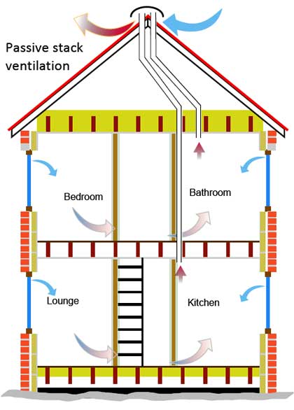 Without the need for any electric fans or control, PSV systems are energy efficient. The amount of ventilation achieved depends largely on the amount of movement of the external air and the external air temperature. Very little control is available with PSV systems although humidity controlled dampers (which need no electrical power) can be fitted in the ducting to prevent over ventilation.
(click the image to the right for a larger version)
A Passive Stack Ventilation system does need careful design and installation as the air movement along the ducting is achieved just by the temperature/moisture in the air. The ducting needs to relatively large (compared with systems using fans to move the air) and as near vertical as possible without sharp bends.
It is really only practical to install Passive Stack Ventilation in a new build or during a major refurbishment. Apart from the ducting, the system includes a roof ridge level vent for external air movements to help extract the stale air.
Trickle vents are required in double glazed units to allow fresh air to enter the building to replace the stale air removed by the stack.
Ducts are conduits or passages used in heating, ventilation, and air conditioning (HVAC) to deliver and remove air. The needed airflows include, for example, supply air, return air, and exhaust air.Ducts commonly also deliver ventilation air as part of the supply air. As such, air ducts are one method of ensuring acceptable indoor air quality as well as thermal comfort.
A duct system is also called ductwork. Planning (laying out), sizing, optimizing, detailing, and finding the pressure losses through a duct system is called duct design.
Materials
Ducts can be made out of the following materials:
Galvanized steel
Galvanized mild steel is the standard and most common material used in fabricating ductwork because the zinc coating of this metal prevents rusting and avoids cost of painting. For insulation purposes, metal ducts are typically lined with faced fiberglass blankets (duct liner) or wrapped externally with fiberglass blankets (duct wrap). When necessary, a double walled duct is used. This will usually have an inner perforated liner, then a 1–2″ layer of fiberglass insulation contained inside an outer solid pipe.
Rectangular ductwork commonly is fabricated to suit by specialized metal shops. For ease of handling, it most often comes in 4′ sections (or joints). Round duct is made using a continuous spiral forming machine which can make round duct in nearly any diameter when using the right forming die and to any length to suite, but the most common stock sizes range evenly from 4″ to 24″ with 6″-12″ being most commonly used. Stock pipe is usually sold in 10′ joints. There are also 5′ joints of the non-spiral type pipe available, which is commonly used in residential applications.
Aluminium
Aluminium ductwork is lightweight and quick to install. Also, custom or special shapes of ducts can be easily fabricated in the shop or on site.
The ductwork construction starts with the tracing of the duct outline onto the aluminium preinsulated panel. The parts are then typically cut at 45°, bent if required to obtain the different fittings (i.e. elbows, tapers) and finally assembled with glue. Aluminium tape is applied to all seams where the external surface of the aluminium foil has been cut. A variety of flanges are available to suit various installation requirements. All internal joints are sealed with sealant.
Aluminum is also used to make round spiral duct, but it is much less common than galvanized steel.
Polyurethane and phenolic insulation panels (pre-insulated air ducts)
Traditionally, air ductwork is made of sheet metal which was installed first and then lagged with insulation. Today, a sheet metal fabrication shop would commonly fabricate the galvanized steel duct and insulate with duct wrap prior to installation. However, ductwork manufactured from rigid insulation panels does not need any further insulation and can be installed in a single step. Both polyurethane and phenolic foam panels are manufactured with factory applied aluminium facings on both sides. The thickness of the aluminium foil can vary from 25 micrometres for indoor use to 200 micrometres for external use or for higher mechanical characteristics. There are various types of rigid polyurethane foam panels available, including a water formulated panel for which the foaming process is obtained through the use of water and CO2 instead of CFC, HCFC, HFC and HC gasses. Most manufacturers of rigid polyurethane or phenolic foam panels use pentane as foaming agent instead of the aforementioned gasses.
Fiberglass duct board (preinsulated non-metallic ductwork)
Fiberglass duct board panels provide built-in thermal insulation and the interior surface absorbs sound, helping to provide quiet operation of the HVAC system.
The duct board is formed by sliding a specially-designed knife along the board using a straightedge as a guide. The knife automatically trims out a groove with 45° sides which does not quite penetrate the entire depth of the duct board, thus providing a thin section acting as a hinge. The duct board can then be folded along the groove to produce 90° folds, making the rectangular duct shape in the fabricator’s desired size. The duct is then closed with outward-clinching staples and special aluminum or similar metal-backed tape.
Flexible ducting
Flexible ducts (also known as flex) are typically made of flexible plastic over a metal wire coil to shape a tube. They have a variety of configurations. In the United States, the insulation is usually glass wool, but other markets such as Australia, use both polyester fibre and glass wool for thermal insulation. A protective layer surrounds the insulation, and is usually composed of polyethylene or metalised PET. It is commonly sold boxes containing 25′ of duct compressed into a 5′ length. It is available in diameters ranging from as small as 4″ to as big as 18″, but the most commonly used are even sizes ranging from 6″ to 12″.
Flexible duct is very convenient for attaching supply air outlets to the rigid ductwork. It is commonly attached with long zip ties or metal band claps. However, the pressure loss is higher than for most other types of ducts. As such, designers and installers attempt to keep their installed lengths (runs) short, e.g. less than 15 feet or so, and try to minimize turns. Kinks in flexible ducting must be avoided. Some flexible duct markets prefer to avoid using flexible duct on the return air portions of HVAC systems, however flexible duct can tolerate moderate negative pressures. The UL181 test requires a negative pressure of 200 Pa.
Fabric ducting
This is actually an air distribution device and is not intended as a conduit for conditioned air. The term fabric duct is therefore somehow misleading; fabric air dispersion system would be the more definitive name. However, as it often replaces hard ductwork, it is easy to perceive it simply as a duct. Usually made of polyester material, fabric ducts can provide a more even distribution and blending of the conditioned air in a given space than a conventional duct system. They may also be manufactured with vents or orifices.
Fabric ducts are available in various colours, with options for silk screening or other forms of decoration, or in porous (air-permeable) and non-porous fabric. The determination which fabric is appropriate (i.e. air-permeable or not) can be made by considering if the application would require an insulated metal duct. If so, an air-permeable fabric is recommended because it will not commonly create condensation on its surface and can therefore be used where air is supplied below the dew point. Material that eliminates moisture may be healthier for the occupants. It can also be treated with an anti-microbial agent to inhibit bacterial growth. Porous material also tends to require less maintenance as it repels dust and other airborne contaminants.
Fabric made of more than 50% recycled material is also available, allowing it to be certified as green product. The material can also be fire retardant, which means that the fabric can still burn, but will extinguish when the heat source is removed.
Fabric ducts are not rated for use in ceilings or concealed attic spaces. However, products for use in raised floor applications are available. Fabric ducting usually weighs less than other conventional ducting and will therefore put less stress on the building’s structure. The lower weight allows for easier installation.
Fabric ducts requires a minimum of certain range of airflow and static pressure in order for it to work.
Waterproofing
The finish for external ductwork exposed to the weather can be sheet steel coated with aluminium or an aluminium/zinc alloy, a multilayer laminate, a fibre reinforced polymer or other waterproof coating.
Duct system components
Besides the ducts themselves, complete ducting systems contain many other components.
Vibration isolators

A duct system often begins at an air handler. The blowers in the air handler can create substantial vibration, and the large area of the duct system would transmit this noise and vibration to the inhabitants of the building. To avoid this, vibration isolators (flexible sections) are normally inserted into the duct immediately before and after the air handler. The rubberized canvas-like material of these sections allows the air handler to vibrate without transmitting much vibration to the attached ducts. The same flexible section can reduce the noise that can occur when the blower engages and positive air pressure is introduced to the ductwork.
Take-offs
Downstream of the air handler, the supply air trunk duct will commonly fork, providing air to many individual air outlets such as diffusers, grilles, and registers. When the system is designed with a main duct branching into many subsidiary branch ducts, fittings called take-offs allow a small portion of the flow in the main duct to be diverted into each branch duct. Take-offs may be fitted into round or rectangular openings cut into the wall of the main duct. The take-off commonly has many small metal tabs that are then bent to attach the take-off to the main duct. Round versions are called spin-in fittings. Other take-off designs use a snap-in attachment method, sometimes coupled with an adhesive foam gasket for improved sealing. The outlet of the take-off then connects to the rectangular, oval, or round branch duct.
Stack boots and heads
Ducts, especially in homes, must often allow air to travel vertically within relatively thin walls. These vertical ducts are called stacks and are formed with either very wide and relatively thin rectangular sections or oval sections. At the bottom of the stack, a stack boot provides a transition from an ordinary large round or rectangular duct to the thin wall-mounted duct. At the top, a stack head can provide a transition back to ordinary ducting while a register head allows the transition to a wall-mounted air register.
Volume control dampers

Ducting systems must often provide a method of adjusting the volume of air flow to various parts of the system. Volume control dampers (VCDs; not to be confused with smoke/fire dampers) provide this function. Besides the regulation provided at the registers or diffusers that spread air into individual rooms, dampers can be fitted within the ducts themselves. These dampers may be manual or automatic. Zone dampers provide automatic control in simple systems while variable air volume (VAV) allows control in sophisticated systems.
Smoke and fire dampers
Smoke and fire dampers are found in ductwork where the duct passes through a firewall or firecurtain.
Smoke dampers are driven by a motor, referred to as an actuator. A probe connected to the motor is installed in the run of the duct and detects smoke, either in the air which has been extracted from or is being supplied to a room, or elsewhere within the run of the duct. Once smoke is detected, the actuator will automatically close the smoke damper until it is manually re-opened.
Fire dampers can be found in the same places as smoke dampers, depending on the application of the area after the firewall. Unlike smoke dampers, they are not triggered by any electrical system (which is an advantage in case of an electrical failure where the smoke dampers would fail to close). Vertically mounted fire dampers are gravity operated, while horizontal fire dampers are spring powered. A fire damper’s most important feature is a mechanical fusible link which is a piece of metal that will melt or break at a specified temperature. This allows the damper to close (either from gravity or spring power), effectively sealing the duct, containing the fire, and blocking the necessary air to burn.
Turning vanes


Turning vanes are installed inside of ductwork at changes of direction (e.g. at 90° turns) in order to minimize turbulence and resistance to the air flow. The vanes guide the air so it can follow the change of direction more easily.
Plenums
Plenums are the central distribution and collection units for an HVAC system. The return plenum carries the air from several large return grilles (vents) or bell mouths to a central air handler. The supply plenum directs air from the central unit to the rooms which the system is designed to heat or cool. They must be carefully planned in ventilation design.
Terminal units
While single-zone constant air volume systems typically do not have these, multi-zone systems often have terminal units in the branch ducts. Usually there is one terminal unit per thermal zone. Some types of terminal units are VAV boxes (single or dual duct), fan-powered mixing boxes (in parallel or series arrangement), and induction terminal units. Terminal units may also include a heating or cooling coil.
Air terminals
Air terminals are the supply air outlets and return or exhaust air inlets. For supply, diffusers are most common, but grilles, and for very small HVAC systems (such as in residences) registers are also used widely. Return or exhaust grilles are used primarily for appearance reasons, but some also incorporate an air filter and are known as filter returns.
Duct cleaning
The position of the Environmental Management Agency (EMA) is that “If no one in your household suffers from allergies or unexplained symptoms or illnesses and if, after a visual inspection of the inside of the ducts, you see no indication that your air ducts are contaminated with large deposits of dust or mold (no musty odor or visible mold growth), having your air ducts cleaned is probably unnecessary.” A thorough duct cleaning done by a professional duct cleaner will remove dust, cobwebs, debris, pet hair, rodent hair and droppings, paper clips, calcium deposits, children’s toys, and whatever else might collect inside. Ideally, the interior surface will be shiny and bright after cleaning. Insulated fiber glass duct liner and duct board can be cleaned with special non-metallic bristles. Fabric ducting can be washed or vacuumed using typical household appliances.
Duct cleaning may be personally justifiable for that very reason: occupants may not want to have their house air circulated through a duct passage that is not as clean as the rest of the house. However, duct cleaning will not usually change the quality of the breathing air, nor will it significantly affect airflows or heating costs.
Signs and indicators
Cleaning of the duct system may be necessary if:
- Sweeping and dusting the furniture needs to be done more than usual.
- After cleaning, there is still left over visible dust floating around the house.
- After or during sleep, occupants experience headaches, nasal congestion, or other sinus problems.
- Rooms in the house have little or no air flow coming from the vents.
- Occupants are constantly getting sick or are experiencing more allergies than usual.
- There is a musty or stale odor when turning on the furnace or air conditioner.
- Occupants are experiencing signs of sickness, e.g. fatigue, headache, sneezing, stuffy or running nose, irritability, nausea, dry or burning sensation in eyes, nose and throat.
Commercial inspection
In commercial settings, regular inspection of ductwork is recommended by several standards. One standard recommends inspecting supply ducts every 1–2 years, return ducts every 1–2 years, and air handling units annually. Another recommends visual inspection of internally lined ducts annually Duct cleaning should be based on the results of those inspections.
Inspections are typically visual, looking for water damage or biological growth. When visual inspection needs to be validated numerically, a vacuum test (VT) or deposit thickness test (DTT) can be performed. A duct with less than 0.75 mg/100m2 is considered to be clean, per the NADCA standard. A Hong Kong standard lists surface deposit limits of 1g/m2 for supply and return ducts and 6g/m2 for exhaust ducts, or a maximum deposit thickness of 60 µm in supply and return ducts, and 180 µm for exhaust ducts. Another UK standard recommends ducts cleaning if measured bacterial content is more than 29 colony forming units (CFU) per 10 cm2; contamination is classified as “low” below 10 CFU/cm2, “medium” at up to 20 CFU/cm2, and “high” when measured above 20 CFU/cm2.
Duct sealing
Air pressure combined with air duct leakage can lead to a loss of energy in a HVAC system. Sealing leaks in air ducts reduces air leakage, optimizes energy efficiency, and controls the entry of pollutants into the building. Before sealing ducts it is imperative to ensure the total external static pressure of the duct work, and if equipment will fall within the equipment manufacturer’s specifications. If not, higher energy usage and reduced equipment performance may result.
Commonly available duct tape should not be used on air ducts (metal, fiberglass, or otherwise) that are intended for long-term use. The adhesive on so called duct tape dries and releases with time. A more common type of duct sealant is a water-based paste that is brushed or sometimes sprayed on the seams when the duct is built. Building codes and UL standards call for special fire-resistant tapes, often with foil backings and long lasting adhesives.
Signs of leaks
Signs of leaky or poorly performing air ducts include:
- Utility bills in winter and summer months above average relative to rate fluctuation
- Spaces or rooms that are difficult to heat or cool
- Duct location in an attic, attached garage, leaky floor cavity, crawl space or unheated basement.